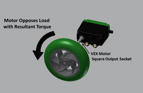
First when we looked at the motor characteristics we looked at specifically at a DC-motor and its specifications such as its unique specs (Stall torque, Stall current , Free current and Free speed).
Stall Torque (N-m) – The amount of load placed on a motor that will cause it to stop moving.
Free Speed (RPM) – The maximum rotational speed a motor will run at when it is under no load.
Stall Current (Amp) – the amount of current a motor will draw when it is stalled.
Free Current (Amp) – The amount of current a motor will draw when it is under no load.
We also looked at relationship between the torque and the load
and also the relationship between the motor current draw and the weight of the load
We also looked at some formulas that you can use to calculate the information needed
Torque Load = (Given Motor Current – Free Current) x Stall Torque / (Stall Current – Free Current)
Current Draw = ((Stall Current – Free Current) / Stall Torque) x Given Torque Load + Free Current
New Value = Spec Value x (New Voltage / Spec Voltage)
Output Torque = input torque * gear reduction
output speed = input speed / gear reduction
For determining “Super” Motor Specs from Multiple Motors combined as one, geared to the same Speed:
Free Speed = SAME
Stall Torque = Sum of all Motor Stall Torques
Stall Current = Sum of all Motor Stall Currents
Free Current = Sum of all Motor Free Currents
|
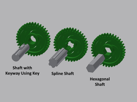
When we moved onto the mechanical transmission we mainly looked at shafts and different types of gears that are used for transmitting power . We first looked at the different types of shafts , there were 4 common shafts which include spline shafts, hexagonal shafts , key way using key shafts and polygonal shafts . Then we looked at the different gears that have unique characteristics which include:
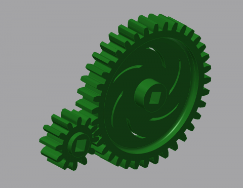
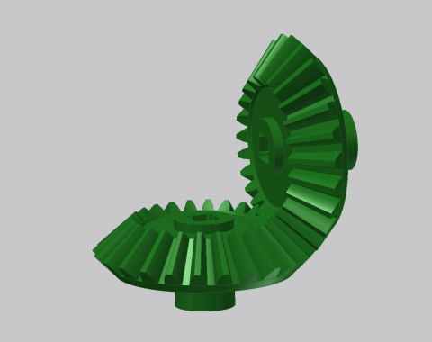
SPUR GEARS: Spur gears transfer motion between two shafts running parallel to each other. Spur Gears are characterized by their teeth, which are straight and parallel to the gear’s axis of rotation BEVEL GEARS: Bevel gears can transmit power between shafts at a variety of angles, but are most commonly used to transmit power 90-degrees CROWN GEARS: Crown gears can mesh with other bevel gears and spur gears (as seen in the example above) so that motion is transferred between shafts with intersecting axes of rotation. WORM GEARS: Worm gears come in pairs: worm gears and worm wheels that mate together to transfer power between perpendicular shafts that have axes of rotation offset from each other. EPICYCLIC (PLANETARY) GEARS: An epicyclic or planetary gear set consists of one or more planet gears moving along an outer ring gear as a central sun gear drives them. As the planet gears are driven, they typically move a planet carrier plate along with them. HELICAL GEARS: Helical gears resemble spur gears, only their teeth are curved in the shape of a helix. These gears can be used to transmit power between two parallel axes of motion, or between perpendicular non-intersecting axes of motion. RACK GEARS: A rack gear is a gear mounted to a straight rod, such that it moves in a linear fashion when torque is applied to it by a spur gear (known as the pinion gear). |
|
Later to finish of this concept we looked at the gear ratios where the relationship of that was larger gear radius/ smaller gear radius and then gear reduction is smaller gear radius/ larger gear radius.
