In this concept we learned about the different types of lifting mechanism , we first looked at the degrees of freedom so basically a degree of freedom refers to a something’s ability to move in a single independent direction of motion. After investigating what degrees of freedom is we moved onto the first type of lifting mechanism which was rotating joints , which relates to the concept of degrees of freedom so it was easier to understand more easier since the mechanism built based on the rotating joints is going to involve some type of gear that is going to drive the mechanism using the help of a mechanism one of the example we looked as a class is shown below

This example shows a 2-jointed arm, which includes a shoulder joint and a wrist joint (note that joints on a robot arm are often named similarly to a human arm). These joints are constructed by locking part of the robot structure onto part of a motion system. In the case shown , the shoulder joint includes an arm locked to the gears of the shoulder gearbox – as these gears turn, the arm turns as well. Similarly, the claw is locked to the gears of the gearbox attached to the end of the arm.
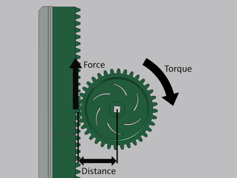
The second type of lifting mechanism that we explored was the linear elevation mechanism , where it converts the rotational motion into linear motion , these types of mechanism does include a rotating joint but it will be used to convert it into a linear elevation here is an example of this mechanism . Here in this example a rack and pinion mechanism is used to drive the elevator. The pinion gear spins at some speed with an applied torque. This torque then applies a linear force at the gear’s pitch circle, which drives the mechanism. There were also three options for the elevator mechanism (rack and pinion mechanism), (chain and sprockets) and (winch mechanism).
The last mechanism that we investigated was a linkage , so again here I learned more about linkages that it can also be used as a lifting mechanism . Linkages are designed to convert some input motion into a different output motion. A linkage typically consists of a series of rigid bodies called links, connected together by freely rotating joints. Typically, one link is fixed and cannot move, and one link is driven in some input motion. Linkages are a fundamental part of machine design because of their ability to create such a wide variety of output motions and their ability to alter the path, velocity, and acceleration of the input. Very precise and somewhat complicated motions can be designed using a simple linkage design. Linkage motions are extremely repeatable. Here is an example of a linkage lifting mechanism , in this particular setup, as the linkage travels through its motion the output link will remain parallel to the fixed link. As such, the claw remains in a consistent configuration. This would be useful for an application where the object manipulator must remain in the same orientation relative to the ground. However, not all 4-bars take this configuration.

